


letzter Beitrag von Sumselbrumsel am
Mein erster VC20 (Oder: Ugh! Kann man bei dem Bild noch was machen?)
- bigby
- Erledigt
-
-
War bei mir auch heut' in der Post. Muss eh gleich noch eine Reichelt Bestellung machen. Bauteile habe ich eigentlich genügend vor Ort, nur der Poti und der 2,7K Ohm Widerstand davon habe ich nix da.
-
-
Müsste dieser sein
-
merci
-

Heute (vielleicht auch schon gestern) kam ein Portrait von Kaiser Karl an und an dem klebte ein nur unwesentlich größerer Brief mit der Platine.

So ein Zufall. Bei mir war Karl heute auch im Briefkasten!

-
Den "Kaiser Karl" hat der Postmann aufgeklebt, der hat meine "Massensendung" dazu genutzt, seine Briefmarken abzuverkaufen, weil sie ihm im Wege waren. Mir war's egal, ich musste ja nicht schlecken.
-
Hi all,
I just found this and have made up a PCB - I'm struggling with making up a cable to connect it to the component in on my TV - I get sync but no picture?
I replaced the VIC20 video DIN for a C64 8 pin type socket and cut the extra 3 pins off. I connected the 2 pins from the PCB to ground, and one of the 3 pins spare on the video connector (pin 6). I made up a cable and connected 2 RCA phono between ground and PIN 5 (Vic Video) and PIN 6 (from the PCB) and connected them to Luma and YP/CR
I changed the jumper to the position to route Luma through the PCB, and I get sync but a black screen?
Maybe I'm building the cable wrongly?
Any help?
Thanks,
KbJ
-

I get sync but no picture?
If there is sync the signal path is OK, sync comes with "luma".
Looks like your VIC 20 does not start and produces only a black screen.
What EXACTLY have you done? Which traces did you cut, if any? Where did you solder what?
Please provide some images.
-
Hi Kinzi,
Thanks for the reply

I haven't cut any traces at all - I made up your PCB with JLCPCB and put it together. I put the 6561 into your PCB and put the PCB in the 6561 socket on the motherboard.
If I change the jumper and connect a comp video cable to the Vic-20 output, I get a standard composite Vic-20 picture (The Vic-20 does boot fine). If I put the jumper towards the outside of the board, I get a clearer picture that's a bit washed out but it goes on and off like my TV can't sync properly. If I connect the 2 RCA cables to YP/CR and Lum on my component in, I get sync but no picture..
The RCA jacks are connected to an 8 pin DIN (I changed the socket for a C64 with 8 pins, cut off the 3 pins your suggested and connected the output of your PCB to one of the unused pins).
Thanks,
KbJ
-
If I connect the 2 RCA cables to YP/CR and Lum on my component in, I get sync but no picture..
The output is S-Video (Y/C), not component (YCrCb/YPrPb).
You need a TV set or monitor with Y/C (aka. "S-Video") input. Is yours capable of displaying S-Video?
-

If I connect the 2 RCA cables to YP/CR and Lum on my component in, I get sync but no picture..
The output is S-Video (Y/C), not component (YCrCb/YPrPb).
You need a TV set or monitor with Y/C (aka. "S-Video") input. Is yours capable of displaying S-Video?
Ahhh.. I'm afraid I'm not up on video standards.. I take it that I'm looking for 2 phono sockets on the back of my TV for S-Video then.. I was confusing it with the 3 component sockets..
thanks,
KbJ
-
Ahhh.. I'm afraid I'm not up on video standards.. I
No problem.

thanks,
You're welcome.
Come back to report success.
-
Hi kinzi,
Thank you for your very kind help - I can now report that I have a Vic-20 with a very nice S-Video output
One thing though - How do I get audio out to the T.V? Do I just take another phono and connect it to the video output (Pin3?) and connect that to that audio in?
Cheers again! Very happy with your excellent PCB mod!
KbJ -
One thing though - How do I get audio out to the T.V? Do I just take another phono and connect it to the video output (Pin3?) and connect that to that audio in?
See https://www.c64-wiki.com/wiki/A/V_Jack ...
Yes, VIC-20 has "Audio Out" on Pin 3 of the DIN jack. Just connect it to "Audio In" of your TV set. The signal level is already right. So you will end with a cable "DIN 5-pin" to three times RCA jack (Luma, Chroma, Audio Out).
Cheers again! Very happy with your excellent PCB mod!
Glad it works now. Have fun.
-
Hello.
I was hoping this type of S-Video mod would exist. I have seen the others but a PCB-based solution is much cleaner.
Does anyone have spare PCBs already made or would I have to order from a PCB fab?
I have seen the archive contents. I am afraid I am not good at identifying the necessary components by photos or schematics alone. Is there a Bill of Materials available?
-
 Alles anzeigen
Hello.
I was hoping this type of S-Video mod would exist. I have seen the others but a PCB-based solution is much cleaner.
Does anyone have spare PCBs already made or would I have to order from a PCB fab?
I have seen the archive contents. I am afraid I am not good at identifying the necessary components by photos or schematics alone. Is there a Bill of Materials available?
Ich habe komplette Bausätze, muß sie aber erst im Marktplatz einstellen
-
 Alles anzeigen
Alles anzeigen
Alles anzeigenHello.
I was hoping this type of S-Video mod would exist. I have seen the others but a PCB-based solution is much cleaner.
Does anyone have spare PCBs already made or would I have to order from a PCB fab?
I have seen the archive contents. I am afraid I am not good at identifying the necessary components by photos or schematics alone. Is there a Bill of Materials available?
Ich habe komplette Bausätze, muß sie aber erst im Marktplatz einstellen
Great! I haven't used the Marketplace before. Let me know what the next step is.
Thank you.
-
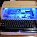
I have finished my kit assembly (complete with 8 pin A/V connector on the PCB) and ready to power on the VIC-20 again.
I am a little confused by the choice for the chroma signal. The instructions say "Choose one of the new pins for "Chroma Out", or change the pinout to be fully C64 compatible". Assuming I do want to be compatible with my existing C64 cables, even those modified already to support an s-video connection, isn't there really only one choice which is to solder the chroma out line to pin 6 on the A/V port? I see you have this pin wired in your example photo's, kinzi.
Then for the GND connection, I can use the closest path to ground? I have removed the RF cage barrier so I can solder a pin directly to one of the PCB holes on the ground rail.
I am also confused by the other wires I saw in your example, kinzi. You have yellow going to pin 6, a red wire going to pin 8 (+5V not used), a hidden black wire and another black wire going nowhere? At the most, I should only need to attach the chroma and GND wires, correct?
Please see my attached assembled kit. Wires not yet soldered (white wire will be for chroma).
-
isn't there really only one choice which is to solder the chroma out line to pin 6 on the A/V port? I see you have this pin wired in your example photo's, kinzi.
That is correct and exactly what I wanted to say:
"Choose one of the new pins for Chroma." (6, 7,

"OR, change the pinout to be fully C64 compatible = Use Pin 6, cut Pin 4/5, connect Pin 1 for Luma."
If you only choose one of the new pins, Luma will be on Pin 4 which ist not fully C64 compatible, the 64 has CVBS on that pin.
[EDIT]
Then for the GND connection, I can use the closest path to ground? I have removed the RF cage barrier so I can solder a pin directly to one of the PCB holes on the ground rail.
You do not have to connect GND again if the croma wire is short enough. The GND pin on the pin header is only there if you want to connect a (long) shielded Chroma connection.
I am also confused by the other wires I saw in your example, kinzi. You have yellow going to pin 6, a red wire going to pin 8 (+5V not used), a hidden black wire and another black wire going nowhere? At the most, I should only need to attach the chroma and GND wires, correct?
I must have a look on my pics first, can't remember ATM, The red wire is almost for sure to replace the +5 V originally residing on pin 1 of the VIC-20 connector. The C64 has +5 V on 7 or 8 (not sure, don't know by heart which).
[/EDIT]